

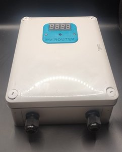
Mk2PVRouter Surplus Energy Diverter
The mk2pvrouter component allows you to retrieve telemetry data
from a Mk2PVRouter diverter and to control it via GPIO switches. It
works with any Mk2PVRouter diverter, as long as the telemetry
feature has been activated on the router itself.
This component can also be used to send data to a non-Home Assistant system via MQTT.
Hardware
Section titled “Hardware”The recommended hardware is the mk2Wifi-C6 expansion module, based on an ESP32-C6-MINI-1. It plugs directly into the mainboard via the TRIG_EXT and UART_EXT pin headers.
The module also provides:
- MISC header — 4 additional GPIOs (GPIO19—GPIO22) for extra sensors or interfaces (e.g. I2C, 1-Wire, digital I/O)
- OLED connector — a Molex SL 4-pin I2C connector (GPIO6 SDA, GPIO7 SCL) for an optional display
NOTE
Any ESP32 board can be used instead of the mk2Wifi module. In that case, adapt the GPIO pin numbers in the examples below to match your wiring.
Wiring
Section titled “Wiring”With the mk2Wifi module, connections are handled automatically through the TRIG_EXT and UART_EXT pin sockets. No extra wiring is needed.
If using a standalone ESP32, connect the TX pin of the Mk2PVRouter mainboard to the RX pin of your ESP module. No TX connection from ESP to the mainboard is needed (communication is one-way).
UART Configuration
Section titled “UART Configuration”The communication uses UART with specific settings: 9600 baud, 7 data bits, even parity, 1 stop bit.
On the mk2Wifi module, the mainboard transmits on UART_TX which is connected to the ESP32-C6 GPIO17 (U0RXD), and GPIO16 (U0TXD) is connected to UART_RX.
NOTE
GPIO16 and GPIO17 are the default UART0 pins on the ESP32-C6, so this configuration uses the hardware UART without requiring any pin remapping.
# mk2Wifi-C6 configurationuart:  rx_pin: GPIO17  baud_rate: 9600  parity: EVEN  data_bits: 7  stop_bits: 1
mk2pvrouter:
Configuration Variables
Section titled “Configuration Variables”Only one mk2pvrouter hub is supported per device.
- id (Optional, ID): Manually specify the ID used for code generation.
- uart_id (Optional, ID): Manually specify the ID of the UART Component if you want to use multiple UART buses.
Available Tags
Section titled “Available Tags”The tags available depend on your Mk2PVRouter configuration. Common tags include:
| Tag | Description | Unit | Notes |
|---|---|---|---|
P | Total power at grid | W | Positive = importing, Negative = exporting |
P1, P2, P3 | Power per phase | W | Three-phase systems only |
R | Mean power for relay diversion | W | Single- and three-phase systems |
V | Voltage (single-phase) | V | Sent in centivolts; converted automatically |
V1, V2, V3 | Voltage per phase | V | Three-phase systems only; converted automatically |
D | Diverted power | W | Single-phase systems |
D1, D2, … | Diversion rate per load | % | Three-phase systems |
E | Diverted energy | Wh | Single-phase systems |
T1, T2, … | Temperature sensors | °C | Sent in centi-degrees; converted automatically |
R1, R2, … | Relay states | 0/1 | 0 = OFF, 1 = ON |
N | No-diversion counter | - | Count of cycles without diversion |
NOTE
Voltage and temperature values are sent multiplied by 100
(centivolts/centi-degrees). For V/V1/V2/V3 and T1, T2,
… tags, the component automatically converts this to volts/°C
before publishing the sensor state, so any filters: you add run
on the already-converted value, just like on any other sensor.
Sensors
Section titled “Sensors”sensor: - platform: mk2pvrouter tag: "P" name: "Power at grid" - platform: mk2pvrouter tag: "V1" name: "Voltage Phase 1" - platform: mk2pvrouter tag: "D1" name: "Diversion rate Load 1"- tag (Required, string): The tag to retrieve from the Telemetry.
- mk2pvrouter_id (Optional, ID):
The ID of the
mk2pvrouterhub to use. Not normally needed, since there is only one hub. - All other options from Sensor.
Sensor defaults (unit, device class, state class, accuracy) are automatically set based on the tag name. You can override any of them by specifying the corresponding option explicitly.
Common tags (same defaults regardless of single- or three-phase setup):
| Tag | Unit | Device Class | State Class | Accuracy | Notes |
|---|---|---|---|---|---|
P | W | power | measurement | 0 | Total power at grid (on three-phase, P = P1 + P2 + P3) |
R | W | power | measurement | 0 | Mean power for relay diversion (single- and three-phase) |
T1, T2, … | °C | temperature | measurement | 2 | Automatically converted from centi-degrees |
R1, R2, … | — | — | none | 0 | Relay state, 0/1 |
Any other tag (e.g. N) | — | — | measurement | 0 | Fallback defaults |
Single-phase tags (bare letter):
| Tag | Unit | Device Class | State Class | Accuracy | Notes |
|---|---|---|---|---|---|
V | V | voltage | measurement | 2 | Automatically converted from centivolts |
D | W | power | measurement | 0 | Diverted power |
E | Wh | energy | total_increasing | 0 | Diverted energy (daily reset counter) |
Three-phase tags (letter + phase/load number):
| Tag | Unit | Device Class | State Class | Accuracy | Notes |
|---|---|---|---|---|---|
P1, P2, P3 | W | power | measurement | 0 | Power per phase |
V1, V2, V3 | V | voltage | measurement | 2 | Automatically converted from centivolts |
D1, D2, … | % | — | measurement | 0 | Diversion rate per load |
NOTE
In the tables above, a — cell means the component sets no
default for that option, so ESPHome’s normal sensor defaults apply
instead; none means the component explicitly clears the state
class for that tag (relay states), which is what "" does when
set from YAML.
NOTE
A tag’s defaults depend on whether the letter is bare or followed
by a number, so D and R do not share defaults with
D1/D2/… and R1/R2/…: a bare D is diverted power in
watts, while D1/D2/… are diversion rates in percent with no
device class. A bare T or an indexed E (such as E1) is not a
Mk2PVRouter output and only gets the fallback defaults.
Binary Sensors
Section titled “Binary Sensors”Relay state tags (R1, R2, …) can also be exposed as binary
sensors: a value of 0 is published as OFF, any other value as ON.
binary_sensor: - platform: mk2pvrouter tag: "R1" name: "Relay 1"- tag (Required, string): The tag to retrieve from the Telemetry.
- mk2pvrouter_id (Optional, ID):
The ID of the
mk2pvrouterhub to use. Not normally needed, since there is only one hub. - All other options from Binary Sensor.
Text Sensors
Section titled “Text Sensors”Any tag can also be exposed as a text sensor, which publishes the raw value exactly as received, without numeric parsing or scaling. Values are limited to 7 characters; longer values are dropped by the hub.
text_sensor: - platform: mk2pvrouter tag: "S_MC" name: "S_MC raw"- tag (Required, string): The tag to retrieve from the Telemetry.
- mk2pvrouter_id (Optional, ID):
The ID of the
mk2pvrouterhub to use. Not normally needed, since there is only one hub. - All other options from Text Sensor.
Complete Example
Section titled “Complete Example”Here’s a complete configuration for a three-phase system using the mk2Wifi-C6 module:
esphome:  name: pvrouter-monitor
esp32:  board: esp32-c6-devkitm-1
logger:  level: DEBUG
wifi:  ssid: !secret wifi_ssid  password: !secret wifi_password
api:  encryption:    key: !secret api_key
ota:  - platform: esphome
uart:  rx_pin: GPIO17  baud_rate: 9600  parity: EVEN  data_bits: 7  stop_bits: 1
mk2pvrouter:
sensor:  - platform: mk2pvrouter    tag: "P"    name: "Total Power"    id: total_power  - platform: mk2pvrouter    tag: "P1"    name: "Power Phase 1"  - platform: mk2pvrouter    tag: "P2"    name: "Power Phase 2"  - platform: mk2pvrouter    tag: "P3"    name: "Power Phase 3"  - platform: mk2pvrouter    tag: "V1"    name: "Voltage Phase 1"    id: voltage_phase1  - platform: mk2pvrouter    tag: "V2"    name: "Voltage Phase 2"  - platform: mk2pvrouter    tag: "V3"    name: "Voltage Phase 3"
Controlling the Mk2PVRouter
Section titled “Controlling the Mk2PVRouter”The mk2Wifi module provides up to 5 trigger/control outputs (D5—D9) connected to the mainboard via the TRIG_EXT header. These GPIOs can control functionalities on the Mk2PVRouter.
NOTE
The solder jumpers for D5—D9 on the mk2Wifi board are open by default. You must close the corresponding jumper for each control output you want to use.
The GPIO mapping on the mk2Wifi-C6 module is:
| Signal | GPIO |
|---|---|
| D5 | GPIO0 |
| D6 | GPIO5 |
| D7 | GPIO4 |
| D8 | GPIO3 |
| D9 | GPIO1 |
NOTE
GPIO4 and GPIO5 are strapping pins on the ESP32-C6. ESPHome logs a
strapping-pin warning at compile time when they are used as
outputs, which is expected here since the module’s PCB dictates
this pin assignment. Add ignore_strapping_warning: true to the
pin config to silence it.
Common control functions include:
- Diversion ON/OFF - Enable or disable energy diversion
- Forced mode - Force the heater ON regardless of surplus energy
- Priority selection - Switch between load priorities
- Temperature override - Override temperature-based controls
switch:  - platform: gpio    pin: GPIO0    name: "Diversion ON/OFF"    inverted: true    restore_mode: RESTORE_DEFAULT_ON
  - platform: gpio    pin: GPIO5    name: "Forced Mode"    inverted: true    restore_mode: RESTORE_DEFAULT_OFF
  # Additional controls (optional)  # - platform: gpio  #   pin: GPIO4  #   name: "Priority Select"  #   inverted: true  #   restore_mode: RESTORE_DEFAULT_OFF  #  # - platform: gpio  #   pin: GPIO3  #   name: "Temperature Override"  #   inverted: true  #   restore_mode: RESTORE_DEFAULT_OFF
NOTE
The Mk2PVRouter digital inputs are active-low by default, so
inverted: true is required for correct operation (ON in Home
Assistant = LOW on the GPIO = active on the router).
TIP
Use restore_mode to define the switch state after reboot:
RESTORE_DEFAULT_ON- Restore previous state, default to ONRESTORE_DEFAULT_OFF- Restore previous state, default to OFFALWAYS_ON/ALWAYS_OFF- Always start in a specific state
Optional Peripherals
Section titled “Optional Peripherals”The mk2Wifi-C6 module supports additional peripherals through its connectors.
OLED Display
Section titled “OLED Display”An I2C OLED display (e.g. SSD1306 128x64) can be connected to the OLED Molex SL connector (GPIO6 SDA, GPIO7 SCL). See SSD1306 for full configuration options.
i2c:  sda: GPIO6  scl: GPIO7
font:  - file: "gfonts://Roboto"    id: roboto    size: 14
display:  - platform: ssd1306_i2c    model: "SSD1306 128x64"    lambda: |-      it.printf(0, 0, id(roboto), "P: %.0f W",                id(total_power).state);      it.printf(0, 20, id(roboto), "V: %.1f V",                id(voltage_phase1).state);
DS18B20 Temperature Sensor
Section titled “DS18B20 Temperature Sensor”The mainboard’s DS18B20 1-Wire signal is passed through the UART_EXT connector to GPIO23. See Dallas Temperature for details.
one_wire:  - platform: gpio    pin: GPIO23
sensor:  - platform: dallas_temp    name: "Water Temperature"
MISC Header
Section titled “MISC Header”The 4 GPIOs on the MISC header (GPIO19—GPIO22) can be used as digital inputs, outputs, or for additional buses.
For example, you can connect the S0 pulse output of an energy meter on the diverted load to track actual diverted energy. See Pulse Counter and Total Daily Energy for full configuration options.
sensor: - platform: pulse_counter pin: number: GPIO19 mode: INPUT_PULLUP id: diverted_power_meter name: "Diverted Power (meter)" unit_of_measurement: "W" internal_filter: 50ms filters: - multiply: 60 # 1000 pulses/kWh -> W conversion - platform: total_daily_energy name: "Diverted Energy Today" power_id: diverted_power_meterMQTT Integration
Section titled “MQTT Integration”WARNING
If you enable MQTT forwarding and do not use the
Native API (i.e., the module is exclusively
used for forwarding data via MQTT and is not connected to any
Home Assistant instance), you must remove the api: configuration
or set reboot_timeout: 0s, otherwise the ESP will reboot every
15 minutes.
If you configure MQTT, you need to define the
MQTT component. Like any other ESPHome entity,
each sensor is published to a topic following this structure:
<topic_prefix>/<component_type>/<object_id>/state, where
<object_id> is the sanitized (lowercase, underscored) version of
the entity’s name. Use state_topic on the entity if you need a
different topic.
mqtt:  broker: 192.168.1.10  port: 1883  username: !secret mqtt_username  password: !secret mqtt_password  topic_prefix: "mk2pvrouter"
mk2pvrouter:
With this configuration, using the sensors named “Voltage Phase 1” and “Total Power” from the Complete Example above, data will be published to topics such as:
mk2pvrouter/sensor/voltage_phase_1/statemk2pvrouter/sensor/total_power/state